Do You Feel the Urge to Build Something? Part 1
Nov 21, 2024
Do You Feel the Urge to Build Something? Part 1
When I was younger, I didn’t think about getting older. If I had thought about it at all, I think I would have assumed that things would start to slow down in what the folks of yesteryear would have laughingly referred to as my “golden years.” Of course, that was before everyone decided that “60 is the new 40.” All I can say is that things seem to be moving faster—and I seem to be working harder—than at any time in my earlier life, and that’s saying something!
One of the things that keeps me sane (don’t say it!) is the fact that I always have a bunch of hobby projects on the go. I also write about these projects, and I engage with people who create their own interpretations of my humble offerings (I pride myself on my humility).
Over the past couple of years, for example, I’ve been writing a series of Arduino Bootcamp columns for the UK’s Practical Electronics hobbyist magazine. As part of this, we’ve developed a clock that employs four 7-segment displays to display the time in HH:MM format. We’ve also used this clock as a platform to experiment with various techniques, like using binary coded decimal (BCD) and multiplexing our displays (if you’re interested in learning more about BCD, you might wish to peruse and ponder my Mysteries of the Ancients column).
Related:What Should We Do With the Inputs to Unused Logic Gates & Functions? (Part 1)
In the November 2024 issue of Practical Electronics, we started by using a single 74LS48 BCD to 7-segment decoder and multiplexing our displays, and we ended by using four latching CD4511 BCD to 7-segment decoders, which relieved us from the task of multiplexing.
I should perhaps point out that, due to the vagaries of print publications, the November 2024 issue hit the streets a month early in the first week of October 2024, thereby maximizing its “shelf life,” as it were.
The reason I mention this is that, just a couple of days ago as I pen these words, I received a plaintive email from someone we will call Ian (because that’s his name). Ian said that he had been following along successfully, from the beginning of the series in January 2023, all the way through to November 2024 until we switched to using the CD4511 devices, at which point everything had gone pear-shaped (i.e., to go badly wrong or to go awry).
The way Ian described things in his email, I feared this was destined to be a stumper. For example, he said his clock seemed to work most of the time, but it refused to present the number 8 on any of its displays (there were other intermittent mischievous manifestations, but we don’t need to worry about those here).
Related:Ode to Bodacious Breadboards, Part 1
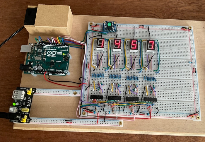
Fortunately, Ian included the image shown below. In fact, there are multiple issues here. For example, the use of woodscrews to secure the breadboards and power strips to the wooden baseboard made my hair stand on end. These are short circuits waiting to happen.

A problem prototype. IAN (FULL NAME WITHHELD BY REQUEST)
Also, powering the Arduino Uno via its 5-V pin is a “No-No.” Although this will work, it’s not advisable because it bypasses the onboard voltage regulator, which means any fluctuations or spikes in the power supply could damage the Arduino.
Ian noted that he had replaced every component on the board to no avail. He’d also removed and replaced all the wires, but this also made no difference. He concluded by saying, “I have checked this a million times and am convinced there are no errors.” Oh Ian, why dost thou tempt the fates by saying things like this?
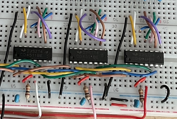
As I said earlier, based on Ian’s description, I was afraid this was going to be a real stumper. Fortunately, determining the cause of the problem turned out to be easy peasy lemon squeezy (and that’s not something that happens very often). Cast your eyes over the CD4511’s data sheet. Now, look at a zoomed-in image of three of the CD4511s below.

A closer look. IAN (FULL NAME WITHHELD BY REQUEST)
Can you spot the issue? I’ll give you a clue, which is that the badly located blue decoupling capacitors have nothing to do with anything. To ensure correct operation, pins 8 and 16 on a CD4511 must be connected to ground (0 V) and power (5 V, in our case), respectively. The ground wires are plain to see, but the power wires are conspicuous by their absence.
Related:Turn Components and Circuit Boards Into Art
I emailed Ian to tell him the news. I also told him that a useful technique is to have a printout of the schematic—including any power and ground connections to ICs—and to mark each component and wire off as it’s added to the breadboard. Ian wryly responded that he had done just this. In fact, his errant power connections were marked on the schematic as being present. He had no idea how this could have come to be.
I do. I’ve done it before myself. It’s all a matter of doing things in the right order. In this case, the right order is to first add a wire, then mark it off in the schematic, then add the next wire… and so forth. Unfortunately, we are sometimes lulled into a false sense of security. “I’m poised to add my four power wires,” one might say to oneself, “so let me mark them off in the schematic.” Unfortunately, you’ve no sooner made your marks than someone calls you to tell you that your supper is ready, or something similar, so you amble off confident in your ability to pick up where you left off on your return. We’ve all “been there and done that,” in one form or another.
Anyway, to cut a long story short (which is opposite to the way I usually like to do things), Ian added the four missing wires. And… it worked! Hurray! Of course, this raises the question as to how Ian’s circuit managed to function at all in the absence of having these ICs powered up. Well, this is down to the magic of the CMOS technology used to implement the CD4511s. These little scamps were pulling parasitic power from their data inputs, but this didn’t provide sufficient resources to illuminate all the segments required to display the number 8.
This reminds me of something similar that happened to the creators of the first ARM processor back in 1985. The designers were aiming at a low-power implementation but—when they put their prototype on the testbench—they were amazed to discover that it appeared to be drawing no power at all! It turned out that they too had forgotten to connect the power wire, and the processor was pulling just enough power to function via tiny leakage currents from its inputs.
I will be regaling you with details relating to other hobby projects in future columns—some of my own and some from my friends. Until then, do you have any of your own DIY projects you’d care to share? As always, I look forward to casting my orbs over your captivating comments, insightful questions, and sagacious suggestions (you can email me at [email protected]).