DIY Logic Probes for Breadboard-Based Prototypes & Projects
Oct 10, 2024
DIY Logic Probes for Breadboard-Based Prototypes & Projects
As I mentioned in my recent columns on the topic of adding pull-up or pull-down resistors to the inputs of unused or partially used logic gates and functions (see Part 1, Part 2, and Part 3), I was fortunate to experience the heyday of 7400-series TTL and 4000-series CMOS integrated circuits (ICs). Many of these little rascals boasted only a handful of primitive logic gates (NOT, AND, OR, etc.) or registers (SR laches, D-type flip-flops, etc.).
The ensuing printed circuit boards (PCBs) could contain hundreds of these little beauties. Believe it or not, our designs didn’t always work the first time, which sometimes resulted in much gnashing of teeth and rending of garb, let me tell you.
Even today, I create a lot of breadboard-based prototypes and projects using simple logic devices of this ilk (see also my Ode to Bodacious Breadboards columns). And, even today, it’s rare for my designs to work the first time. Strange as it may seem, I actually enjoy debugging logic circuits (I really need to get out more), working my way back from any errant outputs, through the logical labyrinth, heading toward the inputs on my quest to discover what I’ve done wrong. Did I use an AND when I should have used a NAND, for example, or did I clock my flip-flop before I’d ensured the desired data was present on its input?
Related:What Should We Do With the Inputs to Unused Logic Gates & Functions? (Part 1)
These days, there are lots of sophisticated debugging tools available, including oscilloscopes and logic analyzers (as an aside, the world’s first logic analyzer, the HP 5000A, was introduced by Hewlett Packard in 1973), but sometimes a simple logic probe can be extremely efficacious.
Logic probes come in all shapes, sizes, and prices. For example, a quick search on Amazon reveals that a rudimentary 3-state logic pen can be yours for only $5, while a somewhat more sophisticated logic level/pulse pen isn’t a bad deal at $23. The only problem with these bodacious beauties is that they allow you to probe only a single signal at a time, but it’s often advantageous to be able to probe multiple signals simultaneously. One solution is to embrace DIY (“do it yourself”) and implement your own.
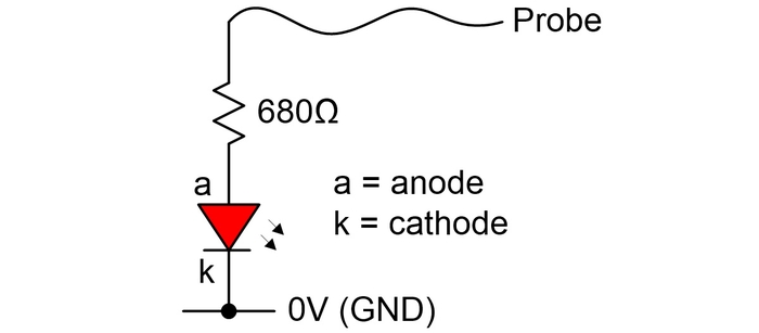
Let’s start at the bottom and work our way up. The simplest (single color) DIY logic probe of all can be created using a single red light-emitting diode (LED) as illustrated below.

Single-color DIY logic probe. CLIVE “MAX” MAXFIELD
I’m assuming that this red LED has a voltage drop of 2 V. Since I don’t want to apply an excessive load on the IC pin that I’m probing, but I still want the LED to glow reasonably brightly (without dazzling me), I’d probably employ a resistor value of 680 Ω (or higher). Using Ohm’s law of V = I * R, rearranging things to give I = V / R, and assuming a 5 V power supply (I often work with an Arduino Uno), we see that this gives (5 – 2) / 680 = ~4 mA of current, which will do for the moment.
Related:What Should We Do With the Inputs to Unused Logic Gates & Functions? (Part 2)
Of course, the LED will only light up if we probe an input or output pin that’s currently at logic 1 (5 V), or if we probe a power pin. The LED will be extinguished if we probe an input or output pin that’s currently at logic 0 (0 V), or if we probe a ground pin.
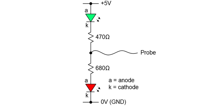
The next level of sophistication is to add a green LED to our probe, thereby allowing us to indicate logic 1 (red) and logic 0 (green) states as illustrated below.

Dual-color DIY logic probe. CLIVE “MAX” MAXFIELD
In this case, I’m assuming the green LED has a forward voltage drop of 3 V. When this LED is fully on, this will result in (5 – 3) / 470 = ~4 mA of current.
Much like your humble narrator (I pride myself on my humility), the way this works is simple. If the probe is applied to a pin carrying a logic 1 value, then the green LED will “see” 5 V on both its anode and cathode terminals, so it will be disabled. Meanwhile, the red LED will experience a 5 V potential difference across its terminals, thereby causing it to light up.
Contrariwise, if the probe is applied to a pin carrying a logic 0 value, then the red LED will have 0 V on both its anode and cathode terminals, so it will be disabled, while the green LED will experience a 5 V potential difference across its terminals causing it to glow.
Related:Ode to Bodacious Breadboards, Part 1
If the probe is left floating, or if it’s applied to a pin in it’s tristate (disconnected) mode, then both LEDs may glow very faintly indeed.
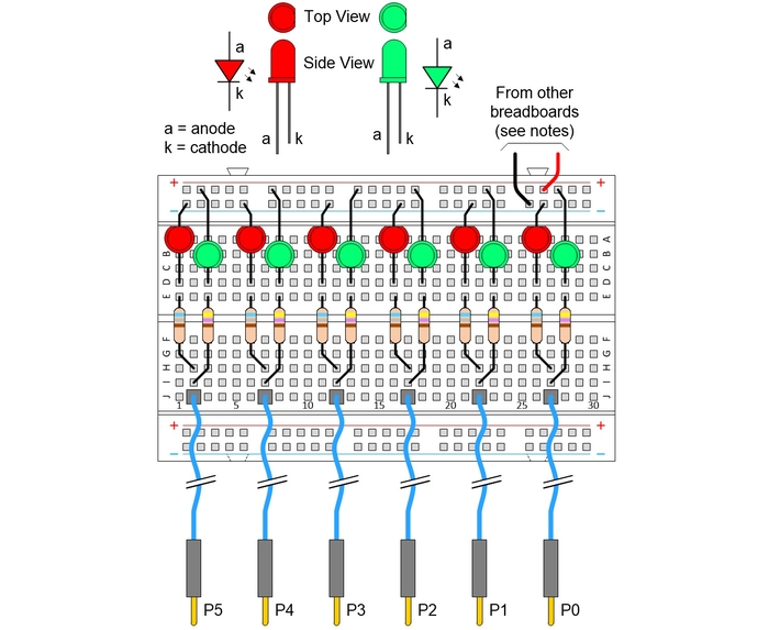
For a recent project, I created six of these little scamps on a half-size breadboard as illustrated below. When I applied these probes to points of interest on my main project, slowing my system clock down to 1 Hz, even simple sequences like a binary count were beautiful to behold.

Six 2-color DIY logic probes on a half-size breadboard. CLIVE “MAX” MAXFIELD
Observe the note in the above image that says, “From other breadboards.” This is the way I typically do things myself, but a separate 5 V supply could be employed. The key point here is that the GND (0 V) rails of all the supplies and all the breadboards are connected, otherwise “it will end in tears,” as they say.
As usual, I find myself with so much more to waffle on about, like how to create an 8-bit probe using just two components, but I fear we must leave that until a future column. As always, I look forward to casting my orbs over your captivating comments, insightful questions, and sagacious suggestions (you can email me at [email protected]).