Using Python to Program Raspberry Pi 5 for IoT Devices, Sensors, & Robotics
Oct 04, 2024
Using Python to Program Raspberry Pi 5 for IoT Devices, Sensors, & Robotics
More often than not, an IoT master device uses the SPI (serial peripheral interface) and I2C (inter-integrated circuit) protocols to exchange data with EEPROMs or sensors that are operating in slave mode. A typical IoT node’s serial interface can be used for just about anything. However, an IoT node’s serial port is most often used to interface with an application running on a personal computer. In addition to EEPROM and sensor duty, SPI and I2C portals can be tasked to provide command and control functionality for robotics applications that involve position sensing and motor control. The Raspberry Pi 5 does not have native analog-to-digital capability and depends on its SPI and I2C portals to communicate with external ADC ICs that are used to enable Raspberry Pi 5-based ADC applications.
The Raspberry Pi 5 can be programmed to function as a SPI master and I2C master device. A dedicated set of serial pins is also available on the Raspberry PI 5’s 40-pin GPIO header. To use the three aforementioned communication portals, all we have to do is invoke the Raspberry Pi 5’s built-in raspi-config (Raspberry Pi software configuration tool) utility to enable the Raspberry Pi 5’s serial, SPI, and I2C interfaces. Once the interfaces are enabled, there is no rule that says we have to connect them to personal computers, EEPROMs, or sensors. We can enhance a Raspberry Pi 5 application by connecting the Raspberry Pi 5’s SPI and I2C interfaces to a microcontroller programmed to function as a SPI or I2C slave. If the application requires it, in addition to the SPI and I2C communication channels, we can also establish a serial connection between the Raspberry Pi 5 and the slave microcontroller.
Related:How to Craft a Raspberry Pi 5 BLE Central Device
I have written three sets of example code that run on a Raspberry Pi 5 and STMicroelectronics NUCLEO-G031K8 development board. The code sets are available for download from the EDTP Electronics website. The Raspberry Pi 5 master code is written in Python, and the NUCLEO-G031K8 slave firmware is coded in C. The NUCLEO-GO31K8 firmware was developed using the STM32CubeIDE. All three NUCLEO-G031K8 examples can be run in release or debug mode from within the STM32CubeIDE.
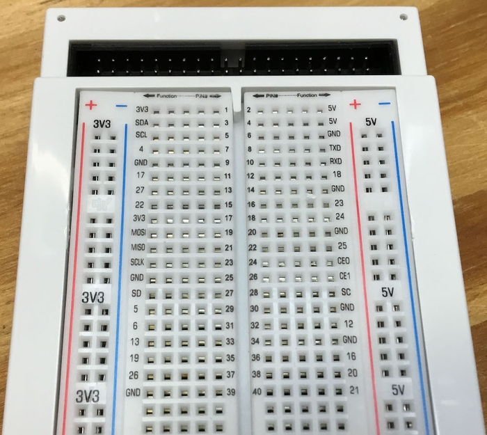
The Raspberry Pi 5-to-NUCLEO-G031K8 GPIO electrical connections are provided by the full-size Vilros breadboard for Raspberry Pi you see in Figure 1 above. As you can see in Figure 2, the Vilros breadboard for Raspberry Pi pins out the Raspberry Pi 5’s 40-pin GPIO header to electrically connected rows on the solderless breadboard. In addition to pinning out the Raspberry Pi 5 GPIO pins to breadboard header rows, the pin number of each of the Raspberry Pi 5’s 40 GPIO pins and their respective functions are printed on each associated breadboard row. Take another look at Figure 2, and you will see the Vilros breadboard for Raspberry Pi is large enough to pin out the Raspberry Pi 5 GPIO and host the NUCLEO-G031K8.
Related:How Can Raspberry Pi 5 Use AI?

Figure 2: The Raspberry Pi 5 GPIO pin numbers and their functions are clearly labeled. FRED EADY
Raspberry Pi 5-to-NUCLEO communication via serial connection
Before we execute any Raspberry Pi 5 or NUCLEO-G031K8 application code, we must enable the Raspberry Pi 5’s serial interface by opening a terminal on the Raspberry Pi 5 and issuing the command sudo raspi-config. In order to enable the Raspberry Pi 5 serial port, we will choose interface options from the raspi-config menu and enable the serial port. At this point we can also go ahead and enable the SPI and I2C interfaces.
The Python serial application code that runs on the Raspberry Pi 5 operates in half-duplex mode and sends single-byte ASCII commands (A = ON and B = OFF) that instruct the NUCLEO-G031K8 to toggle its onboard user LED. The ON command is sent first followed by a 5-second delay, which allows the user to observe the user LED on the NUCLEO-G031K8. Following the delay, the Raspberry Pi 5 sends an OFF command. The Raspberry Pi 5 expects the NUCLEO-G031K8 to interpret the ON/OFF command, illuminate or extinguish the user LED accordingly, and return a status response. The Raspberry Pi 5 Python application determines the validity of the status response and prints the appropriate status message to the console.
Related:Developing Raspberry Pi 5 Apps Using Eclipse
Raspberry Pi 5-to-NUCLEO communication via I2C
The I2C example project includes a file named pi5_i2c_slave.ioc. Opening this file inside of the STM32CubeIDE and choosing I2C1 under the connectivity menu item will reveal the hardware configuration I have chosen for the NUCLEO-G031K8’s I2C1 interface. Within the I2C configuration you will see that the address of the NUCLEO-G031K8’s I2C1 slave interface is set to 32 decimal and operates at 100 KHz in I2C standard mode. There are no options for full-duplex or half-duplex operation as I2C is inherently a half-duplex protocol.
Operationally, the I2C example is identical to that of the serial example. A single-byte hexadecimal command (0xAA = ON and 0xCC = OFF) is transmitted by the Raspberry Pi 5’s I2C master Python application. The NUCLEO-G031K8 receives and parses the incoming byte and toggles its user LED accordingly. Like the serial example, the NUCLEO-G031K8 I2C slave returns a status response that is checked for validity by the Raspberry Pi 5 Python application and the appropriate status message is printed to the console. A logic capture of the I2C LED ON data exchange can be seen in Figure 3.

Figure 3: A 0xAA command illuminates the NUCLEO-G031K8 user LED and generates a 0xBB response. FRED EADY
Raspberry Pi 5-to-NUCLEO communication via SPI
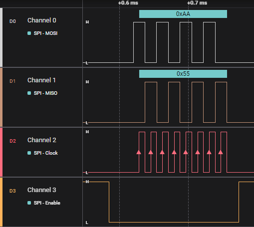
The Python SPI example sends a byte (0xAA) to the NUCLEO-G031K8, which, if verified by the SPI slave, toggles the NUCLEO-G031K8’s user LED. The SPI protocol is full-duplex by nature. With every SPI clock pulse generated by the Raspberry Pi 5, the Raspberry Pi 5 sends a bit to the NUCLEO-G031K8 via the MOSI (Master Out Slave In) pin. The Raspberry Pi 5 also clocks in a bit sent from the NUCLEO-G031K8 over the MISO (Master In Slave Out) pin with every SPI clock pulse. As you can see in Figure 4, the Raspberry Pi 5 transmits 0xAA over the MOSI line and 0x55 is simultaneously received by the Raspberry Pi 5 over the MISO line. If the NUCLEO-G031K8 is the only device on the SPI interface, the SPI Enable signal generated by the Raspberry Pi 5 Master is not required to be sensed by the NUCLEO-GO31K8 Slave device.

Figure 4: This Saleae Logic Analyzer capture details the Raspberry Pi 5 SPI data exchange. FRED EADY
As easy as Pi
The Python and NUCLEO-G031K8 examples are intended to provide a basis for building more-complex applications. The example code also demonstrates how to offload some of the Raspberry Pi 5’s computation load to an external microcontroller-driven device.