What Should We Do with the Inputs to Unused Logic Gates & Functions? (Part 3)
Oct 01, 2024
What Should We Do with the Inputs to Unused Logic Gates & Functions? (Part 3)
It’s my own fault. I have only myself to blame. I knew I was opening a can of worms when I first thought about writing a column on the topic of applying pull-up and pull-down resistors to the inputs of unused and partially used logic gates and functions. When I first put pen to paper (well, fingers to keyboard), I honestly believed I could cover everything in a single column, but it wasn’t long before I saw the need to append “Part 1” onto the end of the title.
Similarly, when I commenced work on Part 2, I was confident we were poised to wrap things up (I even talk about this being a “2-part mini-series” early in that column. It didn’t take long for me to learn the error of my ways.
Just saying “the error of my ways” reminds me of the British rock band Wishbone Ash, which formed in 1969 and is still performing to this day. The title of their song, Errors of My Way, is a nice play on the classic “error of my ways” phrase (thanks to the wonders of the internet, we can listen to this song and peruse and ponder the lyrics; the thought of having access to this type of information at my fingertips still blows my socks off).
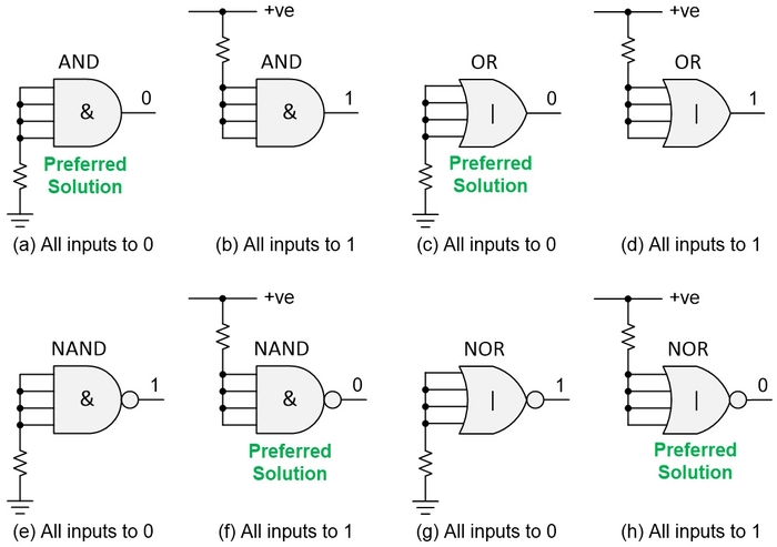
Before we proceed, I’ve received lots of feedback regarding my previous column. As a reminder, if we assume we are working with 4-input AND, NAND, OR, and NOT gates, then I suggested that having a single pull-up or pull-down resistor connected to all the inputs would be advantageous regarding cost. Also, as we know from our discussions in Part 2, given a choice, the input(s) should ideally be pulled such that the output(s) drive low (logic 0) values due to EMC considerations. All this led us to the preferred solutions depicted in the following illustration.
Related:What Should We Do With the Inputs to Unused Logic Gates & Functions? (Part 1)

Preferred solutions when using a single pull-up or pull-down resistor. CLIVE “MAX” MAXFIELD
So, is this truly the way to go? Is this really where we wish to plant our stake in the ground? Well, based on the feedback I received, this would appear not to be the case. The solutions shown above are OK if we are 100% confident that we will never, ever want to use these gates, but are we ever really 100% sure of anything (apart from my awesomeness, of course)?
As a reminder, although we are basing our discussions on the 7400-series TTL and 4000-series CMOS devices of my youth, the concepts presented here are fundamentals that are equally applicable to today’s devices and technologies.
Many of the 7400/4000 devices contain only a handful of primitive logic gates (NOT, AND, OR, NAND, etc.). Our designs circa the 1970s and 1980s could employ thousands of these gates and functions, which meant our printed circuit boards (PCBs) could end up containing hundreds of these simple silicon chips. Almost invariably, this led to a handful of gates and functions remaining unused.
Related:What Should We Do With the Inputs to Unused Logic Gates & Functions? (Part 2)
Just to set the scene, a 74x08 offers four 2-input AND gates, while a 74x21 provides two 4-input AND gates. Now, suppose we are working on a design that requires five 2-input AND gates. We could use two 74x08 devices, but that will leave us with three unemployed 2-input AND gates sitting around, twiddling their metaphorical thumbs, and doing naught but profitlessly consuming power whilst wantonly occupying valuable real estate and on our PCB.
But wait! Let’s further suppose that, when we look around, we see our design employs only one of the two 4-input AND gates in a 74x21 package. In this case, we could coerce the unused 4-input AND to perform the role of a 2-input AND. Some examples of how we could do this are depicted below:

Using a 4-input AND as a 2-input AND. CLIVE “MAX” MAXFIELD
Even though option (a) doesn’t require any pull-up resistors, I don’t like it for reasons we will discuss in our next (and final?) column. The same goes for option (b), but more so, not least that I find its lack of symmetry to be aesthetically displeasing. This leaves us with options (c) and (d). Based on the feedback I received to my previous column, I would go for option (d), even though it requires two resistors.
All of which leads us to the feedback in question, a slightly edited summary of selected items is as follows (all the folks mentioned here have given me permission to use their names and provide their LinkedIn connections).
-
Senior Electronic Design Engineer Daniel Rafferty (BEng [Hons], MSc, MIET) says: “I wouldn’t tie the pins together. I would pull them up or down individually because I may want to use a wire on that gate in a bring-up/debug stage later. The pull-ups or pull-downs should put the gate’s output into stable state that uses the lowest power required.”
-
Retired EDA Platform Architect from Intel Corp. Erik Erlandson says: “Pulling up uses less current than pulling down. If you can do functional in-circuit testing, then pulling each unused input up separately would enable full testing of the component. Detecting a flaw in an unused gate might indicate a flaw in the silicon in general.”
-
Michael Chan, who is Design Manager at Solomon Systech, agreed with and expanded on Erik’s comment with respect to the act of pulling up consuming less current than pulling down, saying: “Yes, PMOS leakage is usually less than NMOS leakage (unless it is custom logic and the PMOS size is especially large).”
-
Eugeny Brychkov, Ph.D. (IIoT | NPD | Embedded | Firmware | System architecture | Electronics | Troubleshooting) said: “IMHO the *only* correct answer is ‘Read the Datasheet,’ either for a specific chip or for a specific device family. You'll never know the tricks used within the chip, therefore any assumptions you make may be wrong. Also note that you must examine the datasheet for *exactly* the chip being used—not a generic datasheet for that general part—because manufacturers may have (significant) differences even within the same part number. As an example, consider the LVC2G17 from TI having partial power down, with the same part number from UMW not having it.”
-
And, last but not least, my old chum Adam Taylor, who is an embedded systems consultant, an expert in FPGA design for mission-critical and safety-critical applications (with a focus on nuclear and space applications), a prolific writer on the topic of FPGAs, and the Founder of the FPGA Consultancy Adiuvo Engineering and Training says: “With my space hat on, each unused pin gets its own pull-up or pull-down resistor.”
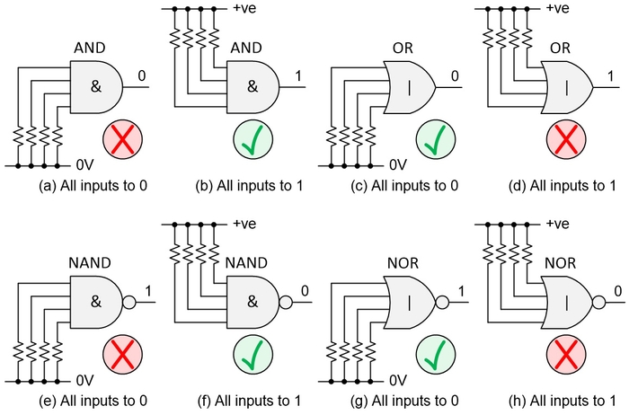
Wait! What? Adam has a space hat!? All I can say is that he’s never showed it to me. Now I want a space hat, too! The bottom line is all these folks agree that if there’s even the faintest possibility you are going to want to use (or test) an unemployed gate at some time in the future, then you need to employ individual pull-up or pull-down resistors on each pin. In the case of 4-input AND, OR, NAND, and NOR gates, for example, this new realization can be summarized as depicted below:

Acceptable solutions when using a multiple pull-up or pull-down resistors. CLIVE “MAX” MAXFIELD
Contrast this to our first image in which we used only one resistor for all the inputs. Taking the AND gate as an example: (a) used to be our preferred solution because it caused the output to go to 0, while (b) was an acceptable alternative. By comparison, when using multiple resistors, option (a) is unacceptable, leaving option (b) as the only solution.
This is, of course, because any input to an AND gate being 0 will drive the output to 0. In turn, this would mean that we could not subsequently (easily) decide to remove say two of the resistors to use this as a 2-input AND because the remaining two inputs will continue to force the output to 0. Similar reasoning applies to the other functions as shown.
Oh, my goodness gracious me, we’ve overrun again, and we’ve still got so much to talk about. Don’t worry, all will be revealed in Part 4. Until that frabjous day, do you have any thoughts you’d care to share on this captivatingly contentious topic? If so, please feel free to email me at [email protected].